

In this project, we will build a Biometric Security System with Arduino & fingerprint sensor. This system will be able to identify someone by their fingerprint and give them entry to a secure area. We will be using an R307 fingerprint sensor module to capture and store fingerprint data.
This data will be used to validate the identity of a person when he/she try to access the secured area. The system will be able to reject or accept the person based on their fingerprint data.
The system will be equipped with an LCD screen to display status messages and an LED to provide feedback. Check my previous post on GSM-Based Home Security System Using Ultrasonic Sensor
Required Material
- Arduino board
- Fingerprint sensor module
- 16×2 I2C LCD
- Relay module
- Push buttons
- LEDs (optional, for visual feedback)
- Jumper wires
- Breadboard;
You can check one of our previous security system projects before building a similar system.
4×4 Matrix Keypad Module
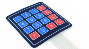
The 4×4 matrix keypad module is an electronic module that allows a user to input data using a set of four rows and four columns of keys arranged in a matrix. It is commonly used in electronic devices such as calculators. The 4×4 matrix keypad module has 16 input values that this module can provide. It uses only eight GPIO pins on a microcontroller, which makes it very efficient.
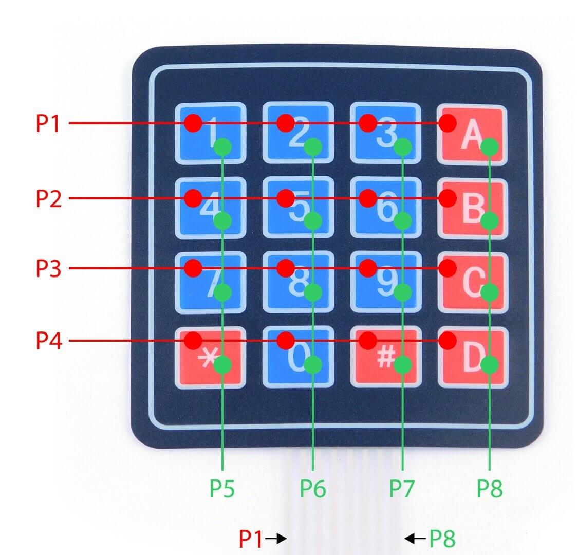
These Keypad modules were made of thin, flexible membrane material. As for the 4×4 keypad module, it consists of 16 keys and is organized in a matrix of rows and columns.
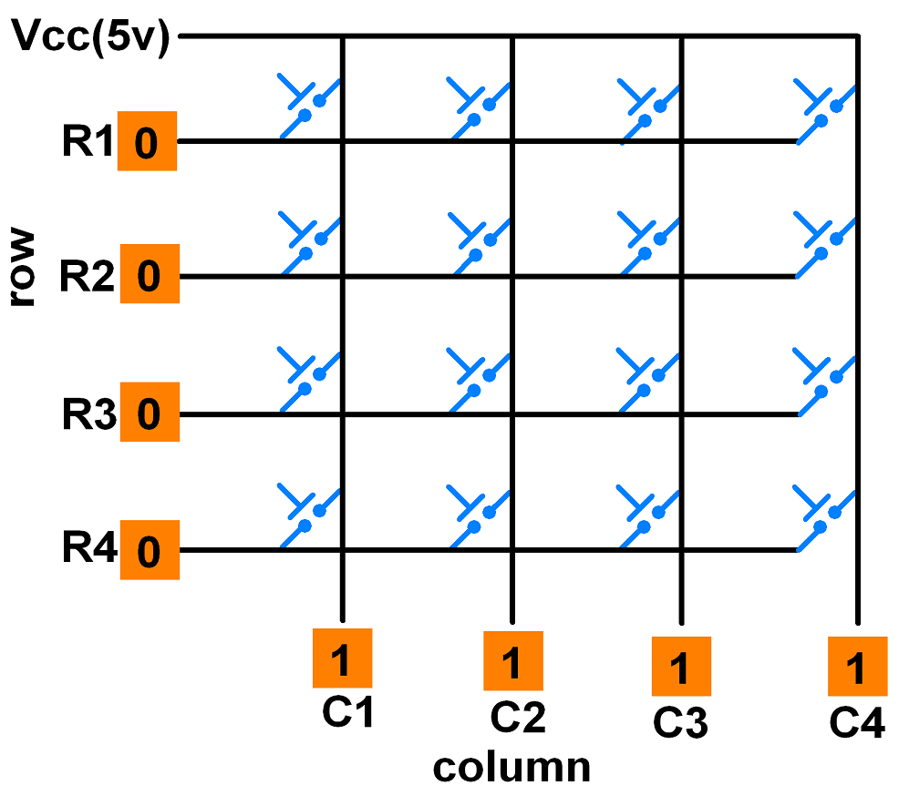
All these switches are connected with a conductive path. Therefore, there would be no connection between rows and columns. Only right when you press a key, then a row and a column make contact.
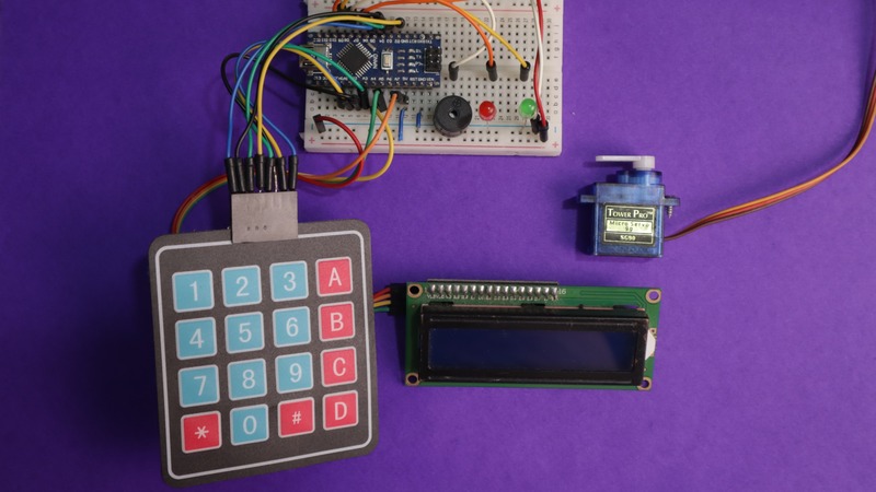
Wiring Arduino Keypad Door Lock Security System
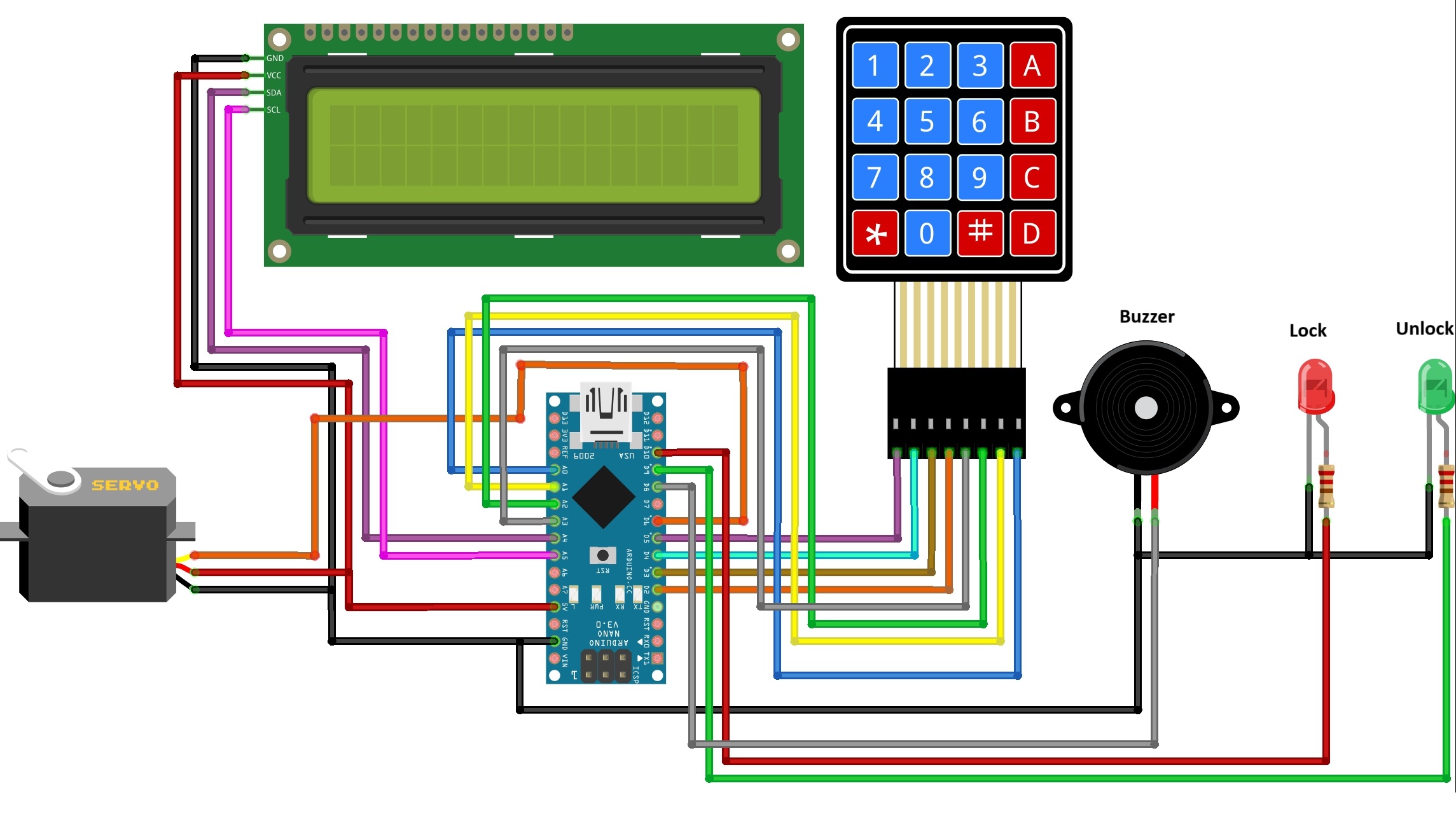
Connect the I2C LCD to Arduino using SDA (A4) and SCL (A5) pins. 4×4 keypad to Arduino, with rows to pins 5, 4, 3, and 2, and columns to pins A3, A2, A1, and A0. Attach a servo motor to pin 6, a buzzer to pin 8, and “Green” and “Red” LEDs to pins 9 and 10, respectively. Connect power and ground as needed for these components.
Connections:
- I2C LCD Display:
- SDA (Data): Connect to Arduino’s A4.
- SCL (Clock): Connect to Arduino’s A5.
- Keypad:
- Rows (4 pins): Connect to Arduino pins 5, 4, 3, and 2.
- Columns (4 pins): Connect to Arduino pins A3, A2, A1, and A0.
- Servo Motor:
- Signal Pin: Connect to Arduino pin 6.
- VCC Connect to Arduino’s 5V.
- Ground: Connect to Arduino’s GND.
- Buzzer:
- Buzzer Positive Pin: Connect to Arduino Pin 8.
- Buzzer Ground (-): Connect to Arduino’s GND.
- LEDs:
- “Green” LED connects to Arduino pin 9.
- “Red” LED connects to Arduino pin 10.
Make the circuit based on the schematic diagram given in the above picture. I have already explained the connection details of each component and module.
Source Code and Libraries
This is the code for our project, which is titled “Password Based Door Lock Security System Using Arduino and keypad is given below. It may be used using Arduino IDE. That final project is uploaded onto the Arduino microcontroller.
Download and install the following libraries:
1 2 3 4 5 6 7 8 9 10 11 12 13 14 15 16 17 18 19 20 21 22 23 24 25 26 27 28 29 30 31 32 33 34 35 36 37 38 39 40 41 42 43 44 45 46 47 48 49 50 51 52 53 54 55 56 57 58 59 60 61 62 63 64 65 66 67 68 69 70 71 72 73 74 75 76 77 78 79 80 81 82 83 84 85 86 87 88 89 90 91 92 93 94 95 96 97 98 99 100 101 102 103 104 105 106 107 108 109 110 111 112 113 114 115 116 117 118 119 120 121 122 123 124 125 126 127 128 129 130 131 132 133 134 135 136 137 138 139 140 141 142 143 144 145 146 147 148 149 150 151 152 153 154 155 156 157 158 159 160 161 162 163 164 165 166 167 168 169 170 171 172 173 174 175 176 177 178 179 180 181 182 183 184 185 186 187 188 189 190 191 192 193 194 195 196 197 198 199 200 201 202 203 204 205 206 207 208 209 210 211 212 213 214 215 216 217 218 219 220 221 222 223 224 225 226 | #include #include #include #include // Include the Servo library #include "SafeState.h" #include "icons.h" /* Define the I2C LCD object */ LiquidCrystal_I2C lcd(0x27, 16, 2); /* Keypad setup */ const byte KEYPAD_ROWS = 4; const byte KEYPAD_COLS = 4; byte rowPins[KEYPAD_ROWS] = {5, 4, 3, 2}; byte colPins[KEYPAD_COLS] = {A3, A2, A1, A0}; char keys[KEYPAD_ROWS][KEYPAD_COLS] = { {'1', '2', '3', 'A'}, {'4', '5', '6', 'B'}, {'7', '8', '9', 'C'}, {'*', '0', '#', 'D'} }; Keypad keypad = Keypad(makeKeymap(keys), rowPins, colPins, KEYPAD_ROWS, KEYPAD_COLS); /* SafeState stores the secret code in EEPROM */ SafeState safeState; /* Define the buzzer and LED pins */ const int buzzerPin = 8; // Change this to your buzzer control pin const int ledOnPin = 9; // Change this to your LED "ON" indicator pin const int ledOffPin = 10; // Change this to your LED "OFF" indicator pin /* Define the servo motor */ Servo lockServo; const int servoPin = 6; // Change this to your servo control pin void setup() { pinMode(buzzerPin, OUTPUT); pinMode(ledOnPin, OUTPUT); pinMode(ledOffPin, OUTPUT); lcd.init(); lcd.backlight(); lockServo.attach(servoPin); // Attach the servo to the specified pin showStartupMessage(); } void loop() { if (safeState.locked()) { safeLockedLogic(); } else { safeUnlockedLogic(); } } void lock() { lockServo.write(0); // Lock position (adjust as needed) safeState.lock(); digitalWrite(ledOnPin, LOW); digitalWrite(ledOffPin, HIGH); } void unlock() { lockServo.write(90); // Unlock position (adjust as needed) digitalWrite(ledOnPin, HIGH); digitalWrite(ledOffPin, LOW); } void showStartupMessage() { lcd.init(); lcd.backlight(); lcd.setCursor(4, 0); lcd.print("Welcome!"); delay(10); lcd.setCursor(0, 1); String message = "Security System"; for (byte i = 0; i < message.length(); i++) { lcd.print(message[i]); delay(70); } delay(500); } // The rest of your code remains the same, as it already handles servo operations. String inputSecretCode() { lcd.setCursor(5, 1); lcd.print("[____]"); lcd.setCursor(6, 1); String result = ""; while (result.length() < 4) { char key = keypad.getKey(); if (key >= '0' && key <= '9') { lcd.print('*'); result += key; } } return result; } void showWaitScreen(int delayMillis) { lcd.setCursor(2, 1); lcd.print("[..........]"); lcd.setCursor(3, 1); for (byte i = 0; i < 10; i++) { delay(delayMillis); lcd.print("="); } } bool setNewCode() { lcd.clear(); lcd.setCursor(0, 0); lcd.print("Enter new code:"); String newCode = inputSecretCode(); lcd.clear(); lcd.setCursor(0, 0); lcd.print("Confirm new code"); String confirmCode = inputSecretCode(); if (newCode.equals(confirmCode)) { safeState.setCode(newCode); return true; } else { lcd.clear(); lcd.setCursor(1, 0); lcd.print("Code mismatch"); lcd.setCursor(0, 1); lcd.print(" Try Again!"); delay(2000); return false; } } void showUnlockMessage() { lcd.clear(); lcd.setCursor(0, 0); lcd.print("Access Granted"); lcd.setCursor(0, 1); lcd.print("Welcome"); delay(2000); unlock(); unlockbuzz(); } void safeUnlockedLogic() { lcd.clear(); lcd.setCursor(0, 0); lcd.print(" Enter # to lock"); bool newCodeNeeded = true; if (safeState.hasCode()) { lcd.setCursor(0, 1); lcd.print(" A = new code"); newCodeNeeded = false; } char key = keypad.getKey(); while (key != 'A' && key != '#') { key = keypad.getKey(); } bool readyToLock = true; if (key == 'A' || newCodeNeeded) { readyToLock = setNewCode(); } if (readyToLock) { lcd.clear(); lcd.setCursor(0, 0); lcd.print(" Wait... "); safeState.lock(); lock(); showWaitScreen(100); } } void safeLockedLogic() { lcd.clear(); lcd.setCursor(0, 0); lcd.print(" Your Password"); String userCode = inputSecretCode(); bool unlockedSuccessfully = safeState.unlock(userCode); showWaitScreen(200); if (unlockedSuccessfully) { showUnlockMessage(); unlock(); } else { lcd.clear(); lcd.setCursor(0, 0); lcd.print("Get Out of Here!"); lcd.setCursor(0, 1); unlockbuzz(); showWaitScreen(1000); } } void unlockbuzz() { // Add your buzzer logic here // For example, play a sound digitalWrite(buzzerPin, HIGH); delay(100); digitalWrite(buzzerPin, LOW); delay(100); digitalWrite(buzzerPin, HIGH); delay(100); digitalWrite(buzzerPin, LOW); delay(100); digitalWrite(buzzerPin, HIGH); delay(100); digitalWrite(buzzerPin, LOW); } void incorrect() { lcd.clear(); lcd.setCursor(0, 0); lcd.print("Access Denied"); lcd.setCursor(0, 1); lcd.print("Try Again!"); unlockbuzz(); showWaitScreen(1000); } |
Working of Arduino Keypad Door Lock Security System
When you turn on the system, it’s in a locked state. The servo motor is in a position that keeps the door closed. The “Red” LED is on, showing that the system is locked.
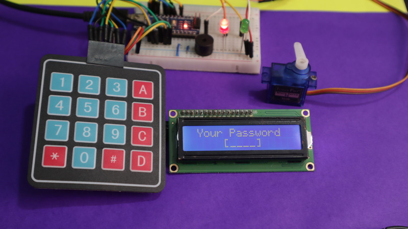
To unlock the system, you need to enter a 4-digit PIN code using the keypad. If you enter the correct code, the system opens. The “Green” LED lights up, allowing access, and a buzzer makes a sound. The servo motor moves to let you through.
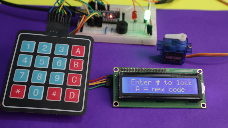
When you want to manually lock the door, press the ‘#’ key on the keypad. The servo motor will be activated to return to the locked position, and the “Green” LED will turn off.
If there’s no code set or you want to replace it, press ‘A’ on the keypad while the system is unlocked. You can then enter a new 4-digit PIN code and confirm it.
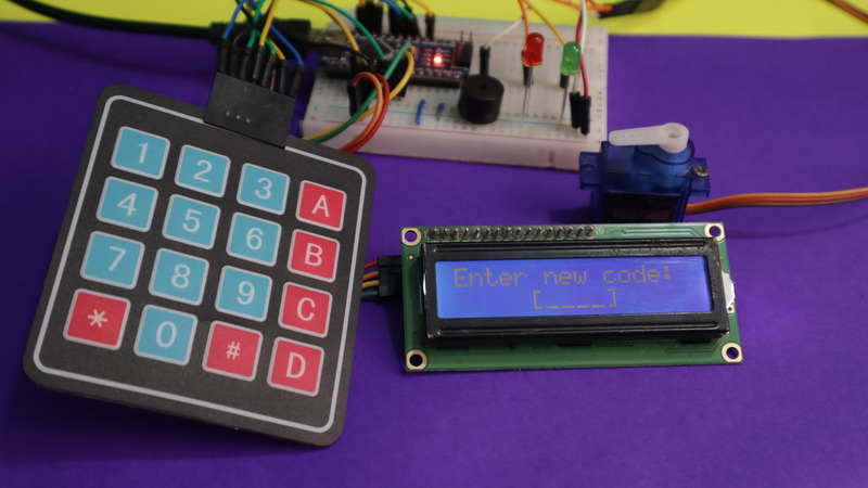
If the input and confirmed code are the same, the system stores the new code for future use.

If you enter the wrong code while trying to unlock, you’ll hear a different buzzer sound. The “Red” LED stays on. You can continue to switch between the locked and unlocked states by entering the code — or pressing ‘#’ — as needed.
The LCD provides directions and results to help guide users through a program.


