
555 Timer Astable Calculator
Calculate frequency, duty cycle, and timing for 555 timer circuits in astable mode.
Charge Time (TH)
--
Discharge Time (TL)
--
Total Period (T)
--
Frequency (f)
--
Duty Cycle (%)
--
Output Waveform
Duty Cycle: --%
Total Period: --
Use our 555 Timer Astable Mode Calculator to quickly calculate frequency, duty cycle, and time period based on resistor and capacitor values.
What is Astable Mode?
In astable mode, the 555 timer keeps turning ON and OFF again and again, making a square wave. It needs two resistors (RA and RB) and a capacitor (C). No trigger input is required — it starts working on its own when powered.
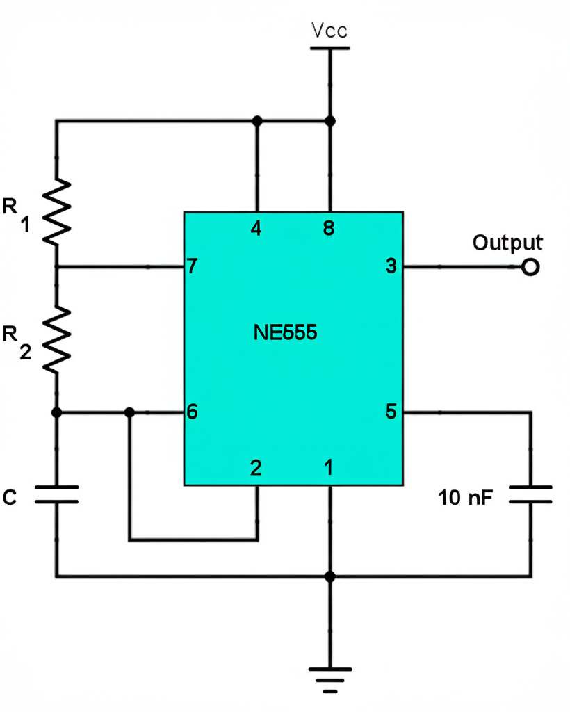
How It Works
- The capacitor charges through both R1 and R2.
- When the voltage across the capacitor reaches 2/3 of the supply voltage, the output goes LOW.
- The capacitor discharges through R2.
- When the voltage drops to 1/3 of the supply voltage, the output goes HIGH again.
- This repeats in a loop, making a square wave signal.
Applications
- LED blinkers
- Tone generators
- Clock pulses
- PWM circuits
- Simple delay circuits
- Flashing lights
How to Use 555 Timer Astable Circuit Calculator
- Enter the capacitor value and select its unit (nF, µF, etc).
- Enter resistor values RA and RB and choose units (Ω, kΩ, MΩ).
- Click “Calculate” to get the results.
- See the timing and waveform details.
Output Parameters
- TH (High Time) – How long the output is HIGH
- TL (Low Time) – How long the output is LOW
- T (Total Period) – One complete cycle
- f (Frequency) – How many cycles per second
- Duty Cycle – Percentage of time output is HIGH
Formulas Used in 555 Timer Astable Circuit Calculator
These are the formulas used for the calculation:


Example Calculation
Given: RA = 1kΩ, RB = 100kΩ, C = 10µF


Component Selection Guide
| Frequency | RA | RB | C | Use |
|---|---|---|---|---|
| 0.1–1 Hz | 10k–100kΩ | 100k–1MΩ | 10–100µF | Slow LED blinkers |
| 1–10 Hz | 10k–47kΩ | 47k–100kΩ | 1–10µF | Warning lights |
| 10–100 Hz | 1k–10kΩ | 10k–47kΩ | 0.1–1µF | Audio tones |
| 100–1000 Hz | 1k–4.7kΩ | 4.7k–10kΩ | 0.01–0.1µF | Alarms |
| 1–10 kHz | 470Ω–1kΩ | 1k–4.7kΩ | 0.001–0.01µF | High-pitched tones |
| 10–100 kHz | 100–470Ω | 470Ω–1kΩ | 100–1000pF | Max 555 frequency |
More Resources
- Download the 555 Timer Datasheet
- Learn about the 556 Dual Timer IC.
- 555 Timer Monostable Calculator
Add A Comment
