
This post will interface a ZMPT101B voltage sensor with ESP32. The ZMPT101B is a voltage sensor used for measuring the RMS voltage of a sinusoidal waveform. The ZMPT101B AC Voltage Sensor Module can measure AC voltages up to 250 volt . It can measure the voltage of a single-phase power line. this is a perfect choice for measuring AC voltage using Arduino/ESP8266/Raspberry PI.
- ESP32 board
- ZMPT101B voltage sensor
- Jumper wires
- Breadboard
- AC voltage source
- OLED
ZMPT101B Voltage Transformer
![]()
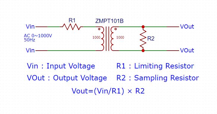
ZMPT 101B is a high-precision voltage transformer used to monitor AC mains voltage up to 1000 volts. This transformer holds up to 4kV per breakdown voltage, the ratio of turns is 1: 1, but this is a current transformer of 2mA: 2mA. It works by feeding a current and taking out a current.
The input current is to be set by the resistor in series R1, and a sampling resistor R2 works in parallel to get the output voltage.
Schematic ZMPT101B Voltage Transformer
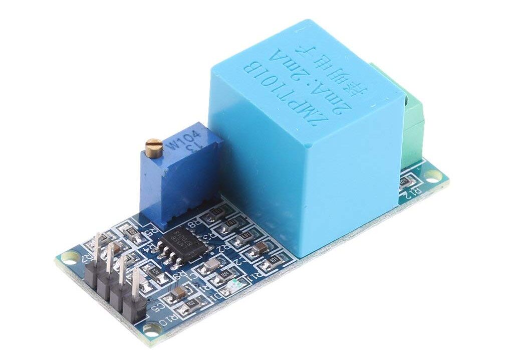
ZMPT101B Voltage Sensor Module
The ZMPT101B is a voltage sensor that measures AC voltages up to 250V. It operates based on the principle of electromagnetic induction. It provides an analog voltage output proportional to the measured AC voltage.
In many electrical projects, an engineer directly deals with measurements with a few basic requirements, like High galvanic isolation, Wide Range, High accuracy, and Good Consistency.
This module provides secure isolation and allows us to apply higher AC voltage as we can measure directly with standard analog inputs, for example on an Arduino UNO.
The output is a 0 to 5V analog signal corresponding to the measured voltage. This sensor module includes the transformer, some up-down input/output resistors are included to avoid damage to sensing circuitry, an opamp is used to amplify the signal, etc.
- Output voltage: Analog 0-5V
- Operating voltage: DC 5V-30V
- Rated input current: 2mA
- Size: 49.5 mm x 19.4 mm
- Operating temperature: 40ºC ~ + 70ºC
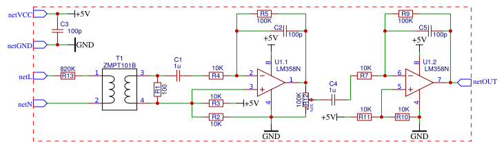
Circuit Diagram & Schematic
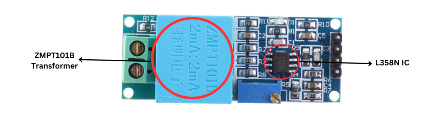 The ZMPT101B module is built with an LM358N IC chip, a few resistors, and some capacitors that help reduce noise or unwanted electrical signals.
Pinout
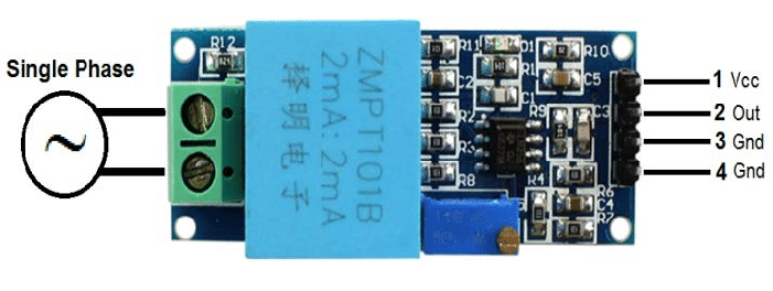
The ZMPT101B voltage sensor generally has four pins:
- VCC: Connects to a 5V DC power source.
- GND: Ground
- GND: Groundswss
- VOUT: Analog output
ZMPT101B Voltage Sensor Features:
- Voltage Measurement Range: Up to 250V AC
- Output Signal: Analog, ranges from 0V to 5V
- Operating Voltage: Supports DC input from 5V to 30V
- Rated Input Current: 2mA
- Physical Dimensions: Compact size of 49.5mm x 19.4mm
- Operating Temperature Range: From 40ºC to +70ºC
- Rated input current: 2mA
- Size: 49.5 mm x 19.4 mm
Applications
- Home Automation
- Industrial Use
- Monitoring power lines
- IoT and Data Logging:
- Smart Energy Management:
- Measuring power consumption
Interfacing ZMPT101B Voltage Sensor with ESP32
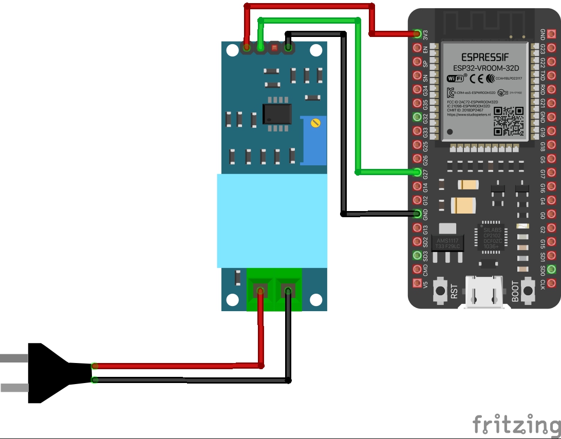
Wiring Connections
| ZMPT101B Pin | ESP32 |
|---|---|
| VCC | 3.3V or 5V |
| GND | Ground |
| VOUT | GPIO 27 |
Code and Library
Download the ZMPT101B Library
- Download the Library:
- Go to the following link: ZMPT101B Arduino Library and download the ZIP file.
- Install the Library:
- Open the Arduino IDE. then Go to Sketch → Include Library → Add .ZIP Library… Select the downloaded ZIP file and install it.
1 2 3 4 5 6 7 8 9 10 11 12 13 14 15 16 17 18 19 20 21 22 23 | #include <Wire.h> #include <ZMPT101B.h> #define SENSITIVITY 500.0f // Adjust this value to calibrate sensitivity #define CALIBRATION_FACTOR 1.49 // Calibration factor to correct the reading (230 / 155) ZMPT101B voltageSensor(27, 50.0); void setup() { Serial.begin(115200); voltageSensor.setSensitivity(SENSITIVITY); } void sensor() { float voltage = voltageSensor.getRmsVoltage() * CALIBRATION_FACTOR; // Apply calibration factor Serial.print("Voltage: "); Serial.println(voltage); } void loop() { sensor(); delay(200); } |
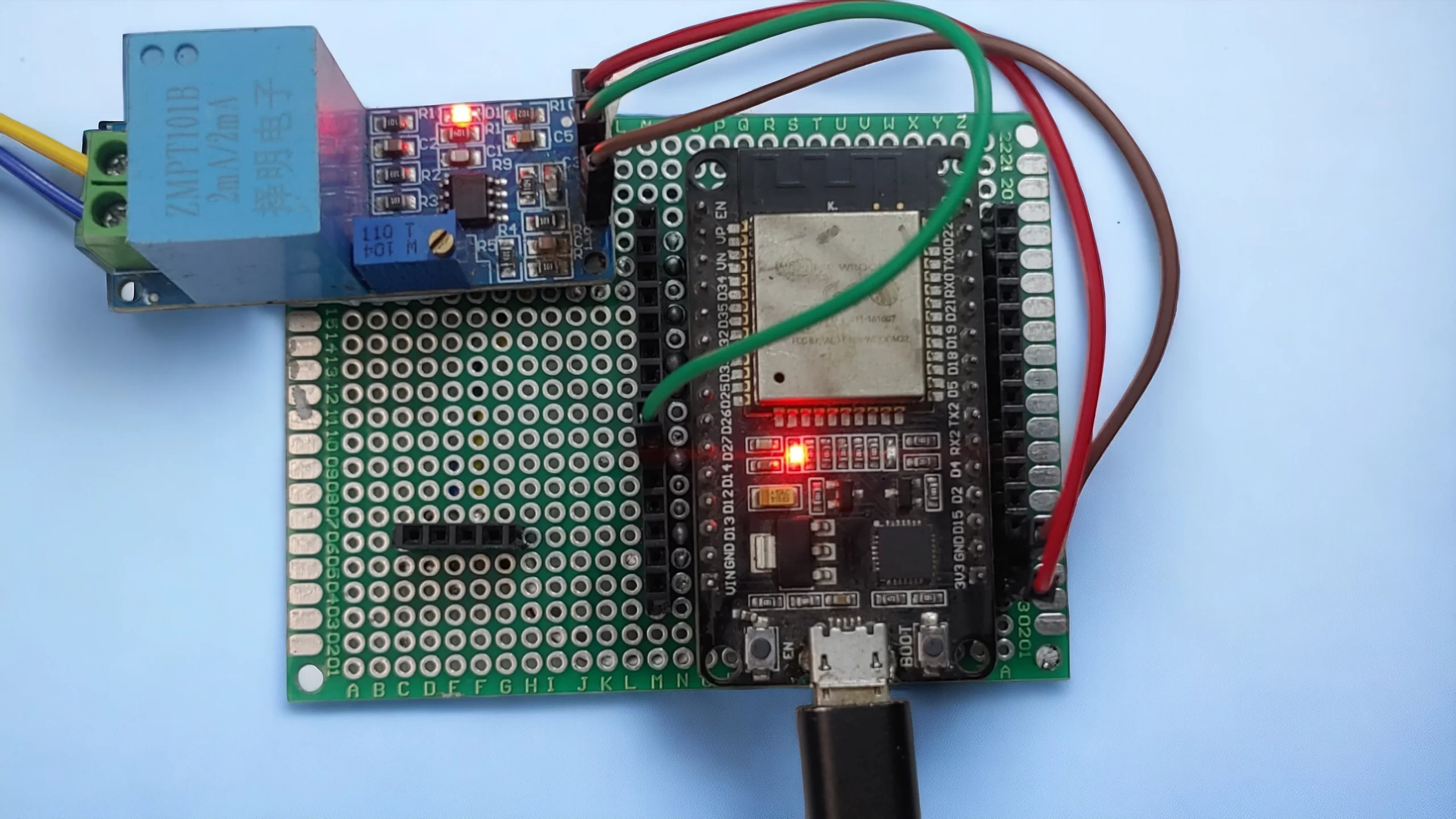
Connect your ESP32 to your computer, Open the Arduino IDE. Select Tools → Board → ESP32 Dev Module Select the correct Port. Click the Upload button.
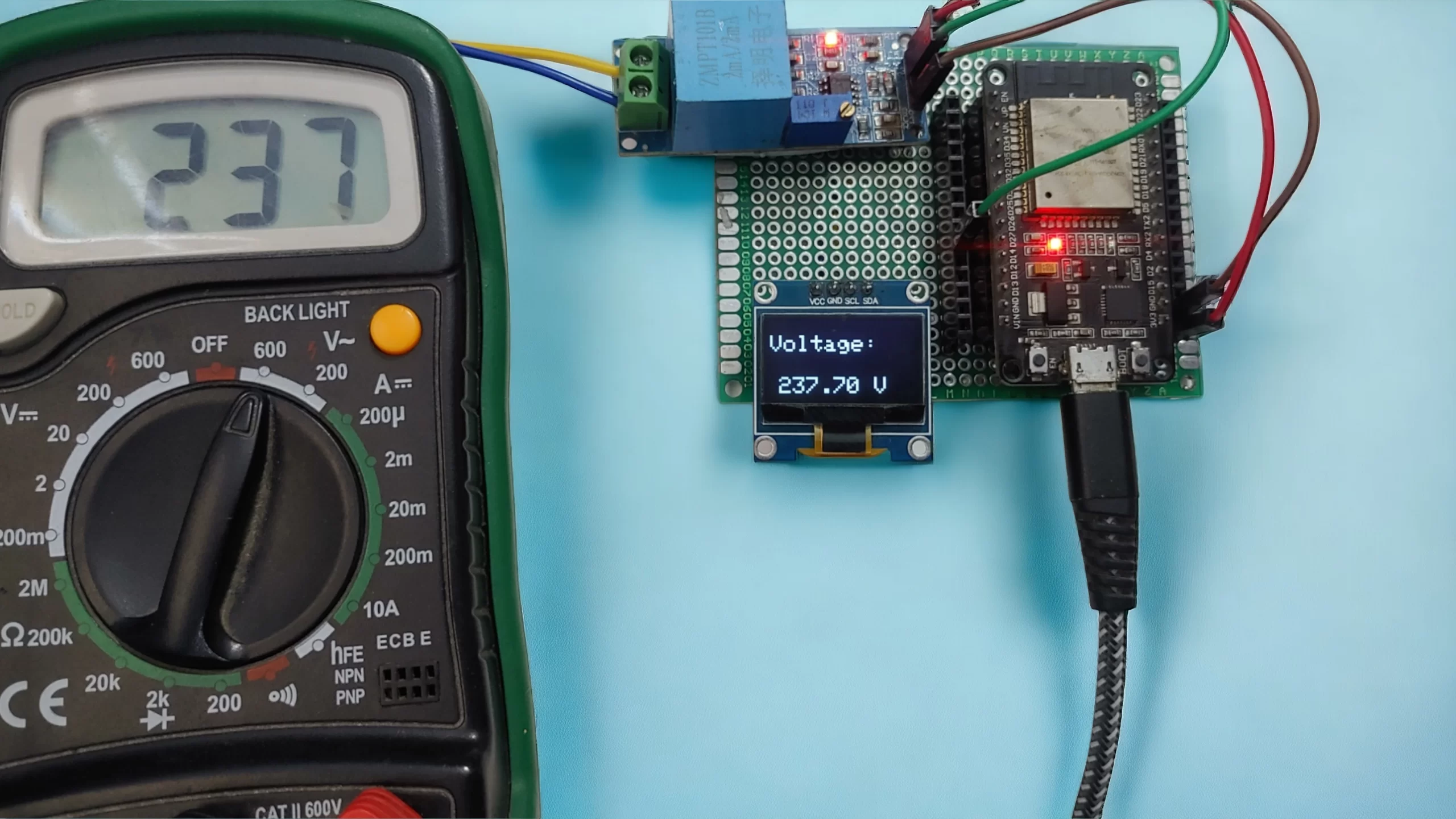
Open the Serial Monitor (115200 baud) and see the voltage.
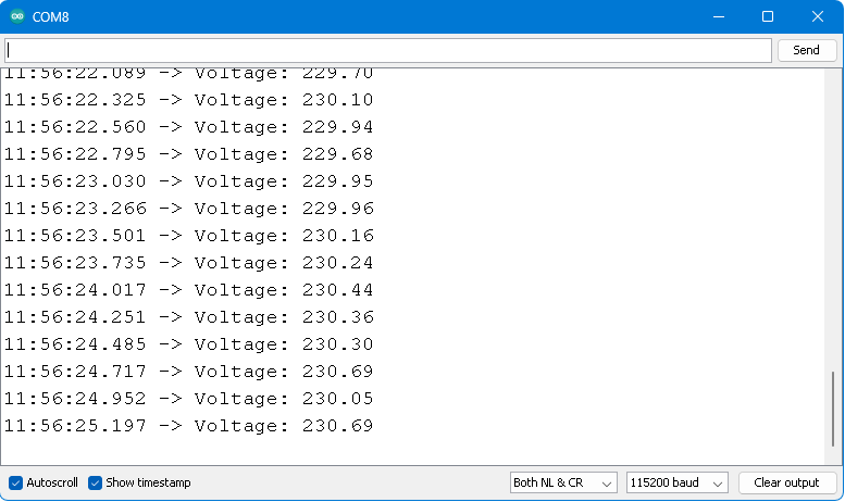
The Serial Monitor showed the correct reading as per the voltage of the Battery.
Making Pa ortable ESP32 AC Voltage Detector with OLED Display
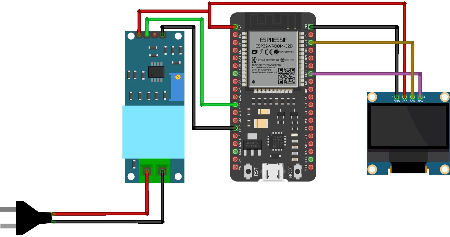
The following is the connection diagram for Interfacing Voltage Sensor Module & OLED Display with ESP32 Board.
The connection is fairly simple. The voltage sensor module has the connection with ESP32 same as earlier. But OLED Display requires 4 connections.
Connect the VCC & GND Pin of OLED to ESP32 3.3V & GND pin. Similarly connect the SDA & SCL Pin of OLED to ESP32 SDA & SCL Pin, i.e 21 & 22.

Source Code
The code requires two libraries for OLED Display. Donwload the libraries from the following link and add it to the Library Folder of the Arduino.
1. Adafruit GFX Library: https://github.com/adafruit/Adafruit-GFX-Library
2. Adafruit SSD1306 Library: https://github.com/adafruit/Adafruit_SSD1306
1 2 3 4 5 6 7 8 9 10 11 12 13 14 15 16 17 18 19 20 21 22 23 24 25 26 27 28 29 30 31 32 33 34 35 36 37 38 39 40 41 42 43 44 45 46 47 48 49 50 51 52 53 54 55 56 57 58 59 60 | #include <Wire.h> #include <ZMPT101B.h> #include <Adafruit_GFX.h> #include <Adafruit_SSD1306.h> // Define the sensitivity and calibration factor #define SENSITIVITY 500.0f // Adjust this value to calibrate sensitivity #define CALIBRATION_FACTOR 1.49 // Calibration factor to correct the reading (230 / 155) // Pin definition for ZMPT101B sensor #define SENSOR_PIN 27 // OLED display settings #define SCREEN_WIDTH 128 // OLED display width, in pixels #define SCREEN_HEIGHT 64 // OLED display height, in pixels #define OLED_RESET -1 // Reset pin (not used with I2C) #define SCREEN_ADDRESS 0x3C // I2C address for the OLED display // Create instances of the ZMPT101B sensor and OLED display ZMPT101B voltageSensor(SENSOR_PIN, 50.0); Adafruit_SSD1306 display(SCREEN_WIDTH, SCREEN_HEIGHT, &Wire, OLED_RESET); void setup() { Serial.begin(115200); voltageSensor.setSensitivity(SENSITIVITY); // Initialize the OLED display if (!display.begin(SSD1306_SWITCHCAPVCC, SCREEN_ADDRESS)) { Serial.println(F("SSD1306 allocation failed")); for (;;); // Don't proceed, loop forever } // Clear the display buffer display.clearDisplay(); } void sensor() { // Read the RMS voltage and apply the calibration factor float voltage = voltageSensor.getRmsVoltage() * CALIBRATION_FACTOR; Serial.print("Voltage: "); Serial.println(voltage); // Display the voltage on the OLED screen display.clearDisplay(); display.setTextSize(2); // Set text size to 2 display.setTextColor(WHITE); // Set text color to white display.setCursor(0, 12); // Position the text on the display display.print("Voltage: "); display.setCursor(8, 48); display.print(voltage); display.print(" V"); display.display(); // Update the display with the new data } void loop() { sensor(); delay(1000); // Delay of 1 second between readings } |
Working
- How to use ZMPT101B Voltage Sensor Module with Arduino
- ESP32 Based Real-Time IoT Energy Monitoring System


")


1 Comment
hi, i tryed this circuit, it reads ac voltage very well
but when i turn off the input(ac main) or if i give 0v ac to measure it shows some stray volatges like 4v.
do u know y ?